An introduction to bending moment calculations
General approach
The calculation of shear forces and bending moments in loaded beams is a common requirement in civil and structural engineering. One common approach to this calculation involves four steps:
- step 1 is to calculate the reactions at the supports;
- step 2 is to imagine cutting the beam and draw a free body diagram of one of the resulting sections the beam;
- step 3 is to calculate the force and moment at the imaginary cut; and
- step 4 is to check the calculation by doing the same on the other section of the beam created by the imaginary cut.
This process relies on the concepts of equilibrium and compatibility and on Newton’s third law of motion. In the examples here, it also makes use of equivalent point loads as a way of simplifying the calculations.
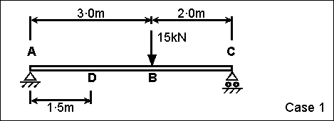
Case 1: simply supported beam with a point load
Case 1 is a simply supported horizontal beam AC with a single point load at B. The beam has a fixed support at A, and a roller support at C. The challenge is to calculate the shear force and bending moment at D.
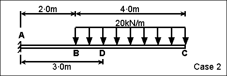
Case 2: cantilever beam with uniform load
Case 2 is a horizontal cantilever beam AC with a uniformly distributed load from B to C. The beam has an encastré support at A, and no other support. The challenge is to calculate the shear force and bending moment at D.
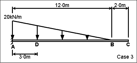
Case 3: cantilever with a triangular load
Case 3 is a horizontal cantilever beam AC with a triangularly distributed load from A to B. The beam has an encastré support at A, and no other support. The challenge is to calculate the shear force and bending moment at D.