Forging Optimisation
Optimisation of Turbine Blade Forging Process using Finite Element Analysis
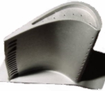
Aerofoil blades are important mechanical components used in aero-engines and require high precision in manufacture. The dimensional tolerances are usually classified in relation to aerofoil shape, thickness and twist along cross-sections and are affected by many factors such as preform shape, temperature, die-elasticity and component springback.
The dimensional tolerances are among the most important manufacturing criteria in the forging of aerofoil blades for aero-engine applications. These are usually classified in relation to aerofoil shape, thickness and twist along cross-sections and are affected by many factors such as preform shape, temperature, die elasticity and component springback. The interaction of all these factors makes design for net-shape forging extremely difficult.
For the purposes of the work carried out at QUB, it is assumed that the preform shape is acceptable and the focus is on the final shape of the forged aerofoil section, and that its overall shape is affected by temperature, die elasticity and material springback. Upsetting of a cylindrical billet is used to demonstrate the compensation method and the feedback mechanisms used to arrive at the final die shape.
Die Shape Optimisation Method
The crux of the method is to run an analysis with a given shape of die, evaluating the final shape due to thermo-elastic effects of the forging process. The results from this analysis is then used to determine what the die shape should be in order to achieve the optimum (required) final blade shape.
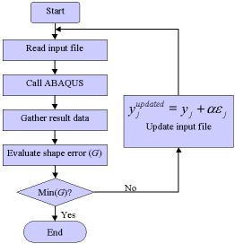
This process is continued with the help of optimisation software and compensation techniques until the final die shape is determined.
Having confirmed the use of the compensation approach on an upsetting process, the next step was to consider an aerofoil blade. Aerofoil blades are usually forged at an elevated temperature, whilst the forging dies have a much lower temperature.
Finite element simulations are undertaken that include:
- forging (which lasts 0.2 seconds)
- removal of the upper die (lasts 0.01 seconds)
- removal of the lower die (0.01 seconds)
- cooling of the component to room temperature (2200 seconds)
Results to Date
The result to date show that a single weight factor, which consider die shape errors in a previous iteration, can be used to control die shape modification. Die shape optimisation can be performed using this factor rather than an array of die coordinates for evaluating shape errors. An optimisation algorithm was used to find the optimal weight factor. For the two cases studied to date (upsetting of a cylindrical billet and forging of an aerofoil section), a fixed weight factor gives equally good results, but with less computational expense.