Design Intent for CAD model assemblies
Introduction
An assembly is where the sub-assemblies and parts which comprise a product come together. The intellectual arrangement of parts in an assembly is a difficult task. Modern CAD environments ontain tools which allow CAD part models to be brought together and problems such as clashes to be discovered. If these problems are not solved before manufacture the physical parts will not assemble ogether without expensive rework.A well-captured design intent for assembly models will enable the designer to design out manufacturing and assembly difficulties at an early design stage.
Aim and Objectives
The aim is to introduce an automated CAD based process defining and capturing design intent in assemblies, and to eliminate clashes which present in a CAD model assembly.
- Identification of parametric relationships between different parts which an assembly is composed of.
- Constraining the assembly according to the identified relationships.
- Automatic identification of parameters which control the clash in an assembly and calculating parametric changes required to eliminate the clash present.
Method
Design Intent
Step 1: Calcukate initial clash in the CAD model assembly (if any).
Step 2: Perturb the parameters in the assmebly model by a small amount (ΔP) and recalculate the clash in the assembly.
Step 3: Calculate the sensitivity of each parameter as the change in clash with respect to the change in parametric value (ΔP).
Step 4: Generate a list of parameters with a sensitivity value along with the features which the parameter represent.
Step 5: Establish any relationships which may exist in the assembly by using the algorithm developed.
Step 6: Constrain the assembly using the identified relationships.
Clash Elimination
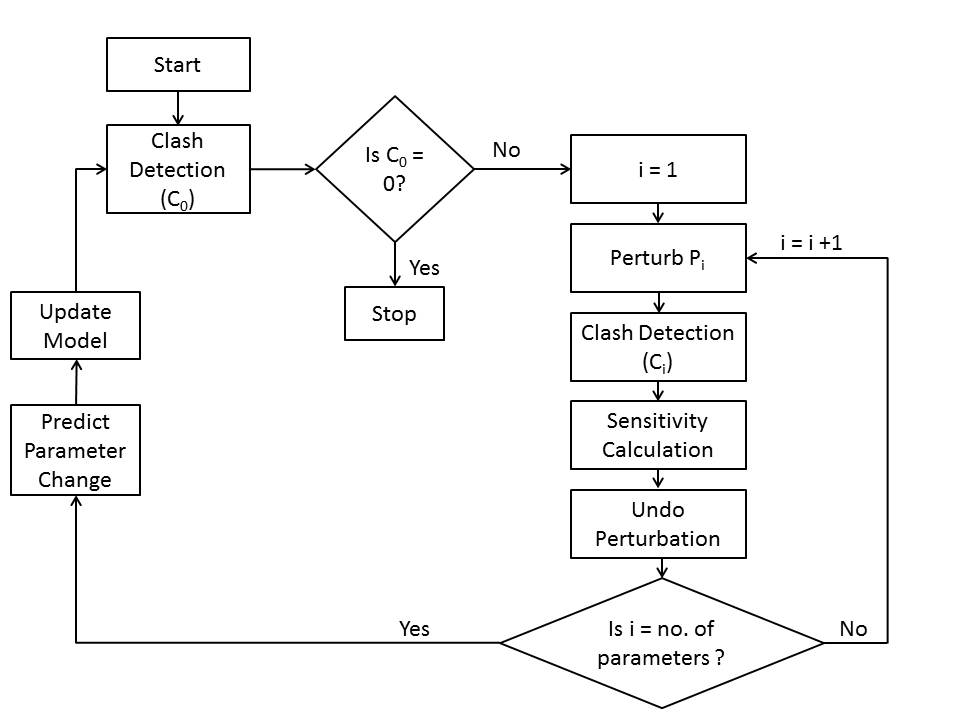
Fig. 1: Process work flow
The fig. 1 shows the method in which sensitivities are calculated for each parameter in the assembly as the change in clash volume due to a change in each component parameter value. These sensitivities are used to calculate the optimum combination of changes in each parameter to eliminate the clashes.
Results
Design Intent
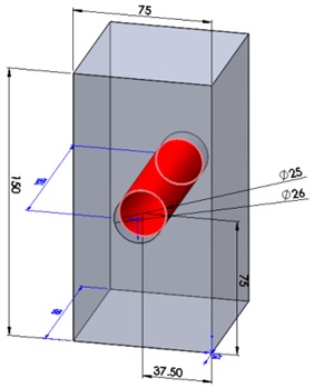
Relationship identified: Shaft diameter = Hole diameter in the housing component
Clash Eliminaton
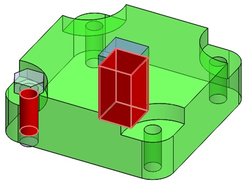
Fig. 2: Bracket Assembly
| Clash Volume (mm3) | |
| Initial Clash 1 | 6200 |
| Initial Clash 2 | 852.16 |
| 1st Iteration | |
| Clash 1 | 19.80 |
| Clash 2 | 0.606 |
| 2nd Iteration | |
| Clash 1 | 0 |
| Clash 2 | 0 |
Table 1: Clash elimination
- Only parameters of central shaft and base components, in Fig. 2, can be changed.
- The bolt (standard component) was left unchanged.
- Clashes eliminated in 2 iterations (71.5 seconds), as shown in Table 1.
Conclusions
- The proposed methodolgy uses sensitivity analysis to highlight design the key parameters which can define and capture the design intent of an assembly.
- The highlighted parameters can also be used to calculate parametric changes which will eliminate the clashes in an assembly.
- Relationships between parameters in an assembly are highlighted at an early design stage and the assembly is constrained accordingly.
- The control of parts and components in an assembly prevents the fabrication and machining of standard components and parts.
- the application of the methodology has a potential to lower design costs by capturing and embedding design intent of an assembly at an early design stage.
??