Managing equivalent representations of design and analysis models
Introduction
With simulation based design being used to create superior products in less time and at lower cost it is essential that the analysis tools employed are completely integrated in the design process. This is emphasised by the fact many companies use multiple analysis tools to get access to different specialist functionality. However, with CAD and CAE tools being developed independently of one another, different analysis and design representations are required. For example, an FEA model requires an abstracted version of the design geometry. In this work, three core technologies, namely Cellular Modelling, Virtual Topology and Equivalencing are used to integrate analysis and design models.
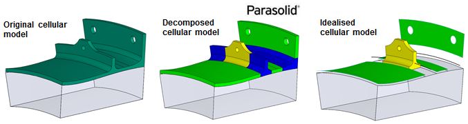
Cellular Modelling
Cells in a non-manifold cellular model have specific simulation significance:
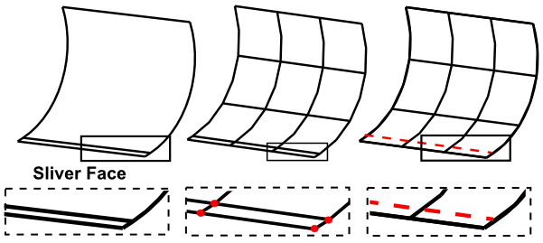
Virtual Topology
Virtual Topology simplifies geometry for analysis purposes without modifying the original geometric model. In this work:
Equivalencing
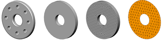
Throughout the design evolution models of various levels of fidelity are required for different applications. In this work the link between these equivalent representations are identified and stored.
For example a given cell in a solid model may be represented as a 3D solid, 3D solid with small features suppressed, 3D mesh or mesh of 2D shell elements with a thickness attribute for a thin-sheet region.
Separate data structure
The non-manifold topology of the cellular model is stored in a separate data structure (relational database) along with virtual topology and equivalencing information.
This data structure stores topology in a generic format allowing it to be accessed by and interact with multiple CAD and CAE packages.
Pre-built queries allow interfaces to be found and the topology interrogated for the database environment.
Integrated design process
Conclusion
Automated tools have been developed allowing multiple CAD and CAE tools, e.g. Parasolid, NX, Abaqus, CADFix to interact with one another so that analysis models and attributes can be transferred between packages without any loss of integrity. These analysis attributes can also be transferred between models of varying fidelity, where adjacencies in lower fidelity models are derived through equivalent relationships in the high level cellular model.