Simulation Intent
INTRODUCTION
- Simulation Intent captures from the outset of the design process how the component is to be idealised and represented in the simulation model
- In this work the thin-sheet and long-slender regions are identified and subdivided out of an aerospace component
- Depending on the simulation intent defined, different meshing strategies can be used to create efficient meshes for the subdivided model
MODEL PARTITIONING USING GEOMETRIC REASONING
- The CADfix Thin-Thick tool is used to identify and extract thin-sheet regions from the model.
- QUB algorithms then use the CADfix API to extract long-slender regions.
- The remaining regions are classed as ‘Complex’.
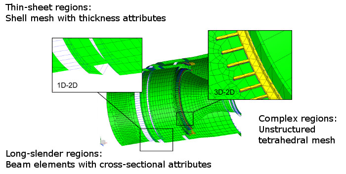
SIMULATION INTENT 1 : USE A REDUCED DIMENSIONAL MESH, WITH ELEMENT TYPE MATCHED TO GEOMETRIC SHAPE
- Idealisation automated in Siemens NX
- Interface data from a cellular model used to automatically tie different regions together
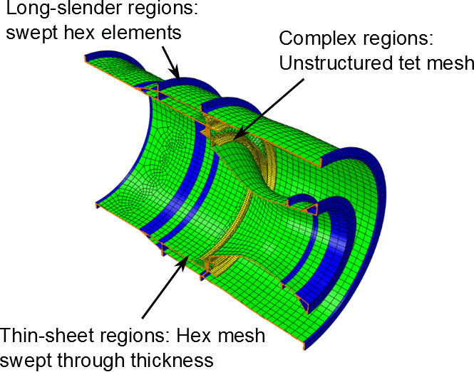
SIMULATION INTENT 2: USE A SOLID MESH, WITH ELEMENT SHAPE MATCHED TO GEOMETRIC SHAPE
CONCLUSIONS
- Geometric reasoning has been used to subdivide aerospace components based on shape
- Simulation intent has been used to define different mesh styles for subdivided regions
To view a video of Simulation Intent being used to create a shell-beam mesh of the above aero engine component, please click below.