MUMPS WP1
In this work package, the objective was to demonstrate that the analyst’s knowledge involved in generating the appropriate simulation models can be captured in an ontology-based simulation intent model which can be used to automate the definition of modelling decisions, managing the analysis data and driving the set-up of the resulting simulation assembly models. The challenge was to support the interoperability of the different designs and associated simulation models in the product development process through a unified DMU. The challenges were not only to propose automatic tools to adapt the geometric models but also methods and tools to facilitate and capture the reasoning of the idealisation decisions.
In this work package, we proposed to evolve the simulation intent concept proposed by QUB (see Nolan and al.[1]) toward an ontology-based implementation. The simulation intent concept involves capturing the high-level modelling and idealisation decisions in order to create fit-for-purpose analysis models. Two of the key capabilities used to define simulation intent are cellular modelling (the partitioning of 3D space into cells of analysis significance to which analysis attributes can be attached) and equivalencing (capturing the links between the different representations of the same region of space). Our objective was to define the ontological concepts and relations required to incorporate the simulation intent capabilities (cellular modelling and equivalencing) into a knowledge-based CAE model (i.e. the unified DMU). This additional knowledge utilises the link between the assembly knowledge and the geometric knowledge to provide a common basis for a unified Digital Mock-Up used to derive CAE models (see WP2).
[1] Nolan, Declan C, Christopher M Tierney, Cecil G Armstrong, and Trevor T Robinson. 2015. “Defining Simulation Intent.” Computer-Aided Design 59: 50–63.
Benefits for the end users (analysts and designers):
- A first benefit is that once the geometrical knowledge is extracted from the CAD assembly and captured in the knowledge database (using the ontology concepts and relations), the analyst can apply automatically inference rules to control the definition of modelling decisions, to manage the analysis data and drive the set-up of the resulting simulation assembly models. Then the analyst focus is on product development rather than simulation model setup, thus directly adding value to the end product.
- A secondary benefit is to increase the reusability of models, to make them more robust to design changes and to maintain the inherent links between multiple analysis models. It is shown in this work package that the equivalencing concepts are integrated in the ontology to maintain links between different analysis representations across multiple analysis models in order to automatically propagate loads, boundary conditions, physical properties, etc.
- In order to bring simulation capabilities upfront in the product development process, more and more designers are encouraged to perform numerical FEM or CFD simulations. For non-specialists, setting-up analyses is challenging. For example, meshing components or defining the correct set of boundary conditions require user expertise. Another benefit of the ontology-based simulation proposed is to help non-specialists to understand the simulation knowledge formalized in the ontology (by highlighting for instance the relations between the simulation objectives and idealisation requirements).
Ontology-based concepts and relations definition:
In this work package, the new vocabulary of cellular modelling and equivalencing has been defined. For example, cells, which simulation attributes can be attached to, are defined as a new concept. New geometric morphologies such as long-slender regions, thin-sheet regions, or 3D thick regions which categorize different mechanical behaviours are added as new concepts.
Relation types link the cells concept to their simulation attributes and idealisation methods. In addition, the concept of “representation” has been defined to allow the cells to be represented by different equivalent representations: 3D volume, 2D shell, 1D beam or 0D mass.
Identification of cyclic symmetry in quasi-axisymmetric components
Following the analysis of use-cases provided by our industrial partner Rolls-Royce (see WP4), we developed a specific tool dedicated to identifying cyclic symmetry in quasi-axisymmetric components. The exploitation of component geometric properties is key to reducing the complexity of the 3D meshing process for finite element (FE) simulation.
Minimizing the number of surfaces and curves used to describe the same geometry makes it easier and quicker to perform any necessary modifications for meshing. Even if the simulation must be performed on the entire component, when the structural component contains symmetry properties, it is helpful to identify and to mesh a part of the model and then to apply symmetry operators to that mesh.
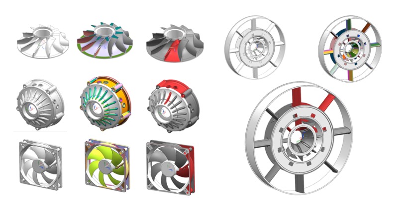
In mechanical engineering, turbomachinery is based on components which are classified here as quasi-axisymmetric, where large portions of the geometry are axisymmetric but they also contain certain non-axisymmetric features. For example, the blades of a turbine or compressor are repeated symmetrically around the axis of rotation, or a casing structure may contain struts repeated at regular angular intervals. The analyst might benefit from these cyclic symmetries to run the simulation only on parts of the model, or to reduce the meshing process by repeating the cyclic sector.
Taking a B-Rep model and the user-defined axis of rotation, the proposed method initially identifies exact cyclic symmetry. The extracted faces are tagged as axisymmetric, cyclic symmetric, pseudo-axisymmetric and non-axisymmetric faces. This information can directly be entered in the knowledge database through the symmetry concept. It can later be used to decompose the model into Hex-meshable repetitive sectors (see WP2). This specific work has been presented to the International Meshing Roundtable 2017 conference in Barcelona.
Boussuge, Flavien, Christopher M. Tierney, Trevor T. Robinson, and Cecil G. Armstrong. "Symmetry-based decomposition for meshing quasi-axisymmetric components." Procedia Engineering 203 (2017): 375-387. (Open access). (link)
Equivalencing
The link between the equivalent representations are maintained by relation types. The most important relation is the “equivalence” relation which was a deliverable of this work package.
Depending on the CAE application, the representation of cells may differ. For example, a global structural analysis of thin components may use shell elements. A local contact analysis may use detailed 3D models. As the fidelity of a cell changes so does its interaction within surrounding cells. The notion of equivalence relationship is used to capture this link. Element types can also vary: 3D Hex, 3D Tet depending on the solver capabilities or the accuracy required. The representation of fluid regions also varies. For example, in CAE software, fluid domains are often extracted as an approximate object representation: a tessellated mesh which is then transformed into a FE/CFD mesh. The implicit true geometry (which could be represented as a CAD B-rep model) does not exist. The CAE software directly creates a mesh model adapted to the simulation requirements.
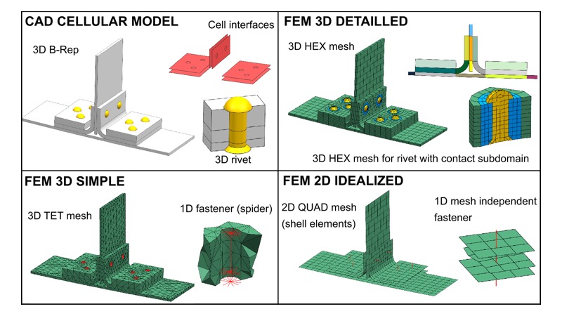
As defined by Nolan et al. ‘Equivalencing’ establishes the link between entities in different design and analysis models which represent the same region of space. The Figure above illustrates four representations of the same assembly structure: a CAD cellular model contains B-Rep components as initially defined in design; a FE 3D detailed model where the solid components are meshed with structured Hex-dominant elements; a FE 3D simple model using Tet elements and a FE 2D idealised model with 2D shell elements. While these models are geometrically different, they represent the same product adapted to a particular type of simulation. Essentially, since these models are representations of the same domain they are considered equivalent to that domain, and by extension to each other.
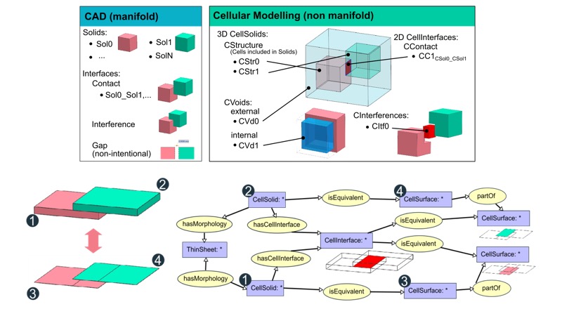
To form the equivalence between multiple representations of the same cell, a relation type is introduced in the ontology: ‘IsEquivalent’. This relation links the cells of the initial cellular model to the equivalent cells of the simplified/idealised CAE models. For example, in the Figure above, the CellSolid1 and CellSolid2 have a thin-sheet morphology type. Within a global mechanical analysis context, these particular thin-sheet cells can be represented by mid-surfaces and have equivalent cells CellSurface3 and CellSurface4. Similarly, the equivalence of interfaces can be captured by utilising the link between the CellSolids, which are explicitly defined in the cellular model as CellInterface. In Figure 9 the dimensional reduction operation leaves no explicit interface between the mid-surface representations. However, this implicit interface is automatically derived from the equivalence relationships. After idealisation the interface is mapped to its equivalent faces using the same ‘IsEquivalent’ relation. In this equivalence instance, the non-manifold interface is equivalent to two distinct manifold faces in the idealised analysis representation. These two manifold faces are part of CellSurfaces of their parents’ mid-surfaces. Hence, in this dimensionally reduced scenario, the interfaces between mid-surfaces can be automatically derived from their equivalent cells linking the initial solid interface.
Implementation and software architecture
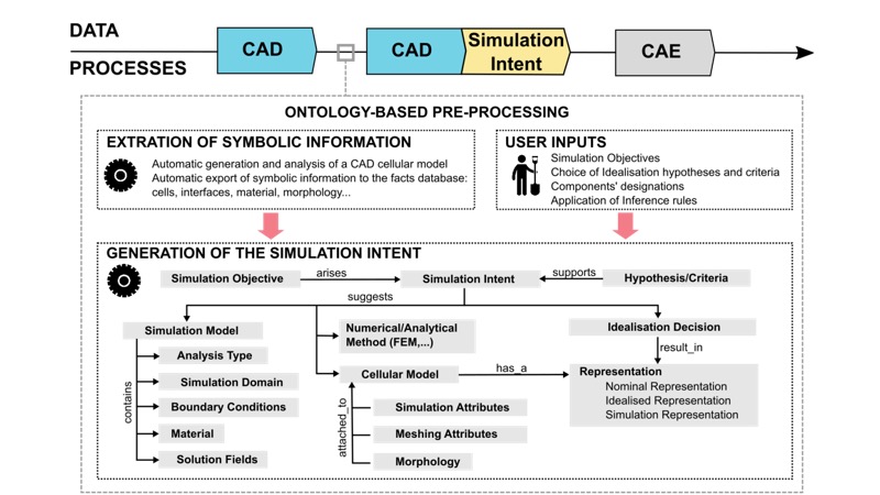
Automatic processes have been developed to capture and structure the knowledge extracted through the simulation intent technologies in the ontology-based application. The initial input is a CAD assembly model. Following the generation of an equivalent B-Rep Cellular Model, the first phase automatically extracts the symbolic information of the Cellular Model and stores it in a triple-store knowledge database. For example, information on cell adjacency, material, etc., is exported. Then, the analyst can define/formalise the simulation objectives, select hypotheses and apply modelling practices as ontology rules on the extracted data. New facts are inferred from the inference rules selected by the user. As an example, regions to idealise will have a new specific idealisation simulation attribute attached following the application of an idealisation decision rule. Interfaces between solids and fluids can also support certain boundary condition simulation attributes, e.g. the temperature and pressure on the solid from the fluid. As an example, accurate and efficient thermo-mechanical modelling is key to understanding the interactions between gas paths, cooling flows through seals and mechanical stress in gas turbine engines.
Here, to maintain the compatibility of the proposed ontology with the one developed by (Vilmart, Léon, and Ulliana 2018)[1], the same software architecture is used. With the help of Grenoble University (academic partner), we developed the ontology concepts and relations are defined in Cogui (CoGui 2018)[2] developed by the GraphiK Inria team and exported as an RDF (W3C Working Group 2014)[3] file to a JENA (JENA 2018)[4] server.
[1] Vilmart, Harold, Jean-Claude Léon, and Federico Ulliana. 2018. “From CAD Assemblies toward Knowledge-Based Assemblies Using an Intrinsic Knowledge-Based Assembly Model.” Computer-Aided Design and Applications 15 (3): 300–317. https://doi.org/10.1080/16864360.2017.1397882.
[2] CoGui. 2018. “Graph-Based Ontology Reasoner.” 2018. http://www.lirmm.fr/cogui/.
[3] W3C Working Group. 2012. “OWL 2 Web Ontology Language Document Overview (Second Edition).” 2012. https://www.w3.org/TR/owl2-overview/.
———. 2014. “Resource Description Framework Schema 1.1.” 2014.
[4] JENA, Apache. 2018. “A Free and Open Source Java Framework for Building Semantic Web and Linked Data Applications.” 2018. https://jena.apache.org/index.html.
As an input of the simulation preparation process, we use a STEP file containing the geometrical and topological information about the CAD assembly model. This file is read by the Parasolid CAD modeller to generate the corresponding cellular model. The symbolic information is automatically extracted from the cellular model, then stored and processed in a JENA knowledge base describing the CAE-oriented ontology as RDF triples. For example, each CellSolid generates an individual, a material is attached to this individual using a relation ‘HasMaterial’. Then, the CoGUI reasoner infers the new RDF triples from the set of pre-defined rules. These pre-defined rules can be used to infer functional designation (see next paragraph) or to derive automatically idealisation decisions for FEM simulation (see WP2). The new symbolic information automatically generated by the reasoner is then used to drive the automatic geometric transformation operators in the CAD/CAE software.
Application of inference rules:
In addition to the CoGUI reasoner capability, a conceptual graph editing tool is available to design the inference rules. Changing these rules allows the user to quickly test and iterate different modelling practices. Concretely, the CAD assembly is enriched with calculated interfaces between components to which analysis attributes can be attached (contacts, interferences and gaps). Fluid domains (not currently described in the DMU) are extracted as new solid bodies and integrated at the assembly level. Then, each component’s shape is analysed to identify shape properties which can be exploited in the analysis model setup (e.g. reflective and cyclic symmetry). These symmetry properties are exploited to identify repetitions of components as well as repetitions of group of components (e.g. linear, circular occurrences of a bolted junction). Finally, once these connections have been established in the design space, as well as geometric properties at the assembly level, functional behaviour in the assembly can be inferred using inference rules. Example applications include component designation: bearings, blades, etc. or sub-assembly designation: bolted junctions etc...
The deductive reasoning is made by an inference engine, here CoGUI (CoGui 2018), which applies a set of rules selected by the user on the set of symbolic information (generation of facts) automatically extracted from the CAD model. The inference rules are based on the ‘Hypothesis/Conclusion’ logic form. The ‘Hypothesis’ and ‘Conclusion’ are defined interactively in the CoGUI software. By defining a graph pattern to search for in the symbolic information extracted from the cellular model, the reasoner can generate new symbolic information to be read by the CAD/CAE software.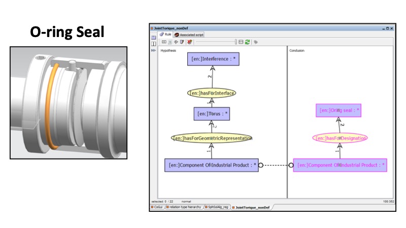
This Figure illustrates an inference rule designed to identify O-Ring seals in the DMU. Here when a solid has a specific toroidal geometry and is in interference with another component, the solid is marked has a having a functional designation O-Ring Seal.
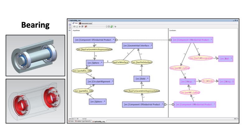
This Figure shows another example of inference rule to derive functional information. Here the bearings are identified by looking at circular repetition of solids having a spherical geometric representation. Finally, this new information is entered in the knowledge database and new rules can be used to derive Finite Elements Models (see WP2).