MUMPS WP3
The objective of this work package was to integrate FEM results into the unified DMU. Following our discussions with our industrial partner, it appears that a bottleneck in current simulation process was to transfer the results of a given simulation as boundary conditions to a new simulation. For example, for an aero engine, the difficulty is to map the thermal results of a 2D axisymmetric simulation to a more detailed 3D simulation. To support this scenario, we developed a tool to automatically generate a 2D axisymmetric model from a given 3D CAD component in order to generate equivalent geometric models where the link between 2D and 3D is maintained.
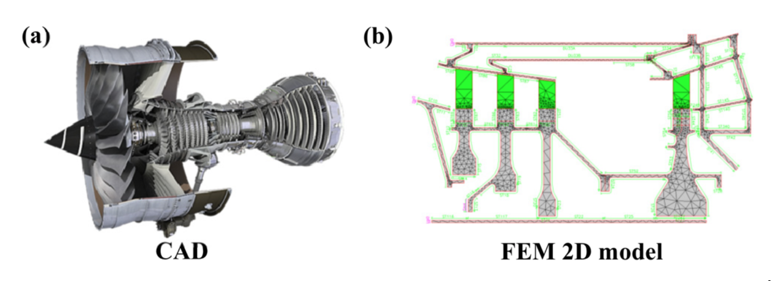
Making the link between 3D models and 2D axisymmetric model
Axisymmetric models are very common in structures which involve rotating components, such as a gas-turbine engines or turbo-machinery. In the design phase, the particular axisymmetric shape of such structures allows analysts to model and simulate a whole gas-turbine using a reduced 2D FEM model. This 2D axisymmetric FEM model contains fewer degrees of freedom than full 3D FEM models and hence reduces time and simulation effort. It is current industrial practice during gas-turbine engine development process to quickly iterate design changes by simulating the different running configurations on this reduced 2D model. Although simulation iterations can be carried out on the 2D model by changing geometric parameters and boundary conditions, one bottleneck for analysts remains the generation of the initial 2D geometry from the reference 3D detailed CAD. At present, CAD systems provide fully detailed 3D geometric models as input for analysis. However, converting complex CAD structures, which are constantly evolving during the product development process, into 2D CAE models, which are efficient to run and yet sufficiently accurate for their application, is extremely time-consuming. Analysts spend considerable time to build the 2D models and to identify the geometric regions which are significant for their analysis and those which are judged not to have much influence on the simulation results.
Moreover, while the automatic geometric updates based on model parametrization is available in CAE software to iterate design changes, the exchange of information between 3D CAD design models and 2D CAE models remains difficult. Indeed, the link between 3D CAD and 2D CAE is lost in the creation of the initial 2D geometry. This makes it difficult to: a) reflect geometric changes from 3D CAD to 2D model; b) transfer the 2D simulation results as CAE boundary conditions for more detailed 3D FEM (global to local refinement); c) automatically define boundary conditions on the 2D model corresponding to particular regions of the 3D assembly (e.g. thermal contacts between components or fluid/structure interfaces).
In this work package we proposed a geometric method to automatically produce a 2D axisymmetric analysis model from a given 3D CAD B-Rep solid. The output is a 2D B-Rep model consisting of connected 2D domains which maintain the link between the initial 3D CAD and the 2D CAE model. Mapping 3D faces/edges to their 2D corresponding domains helps to reflect design changes and map simulation results.
For each 2D domain, the thickness ratio represents the percentage of volume occupied circumferentially by the equivalent 3D geometry. For example, let us consider the blades of a turbine. The thickness ratio will be less than 100 percent to take into account the void regions where the air is passing through. Setting up this parameter is particularly complicated for geometric regions where material is not constant along the axis of rotation, e.g. for non-axisymmetric features used to mount external systems on the engine casing. In our approach, the thickness ratio metric is automatically calculated from the 3D model and transferred to the 2D model. This enables the user to select the subset of geometry that is the most meaningful for a specific 2D simulation, e.g. for thermomechanical FEM simulation
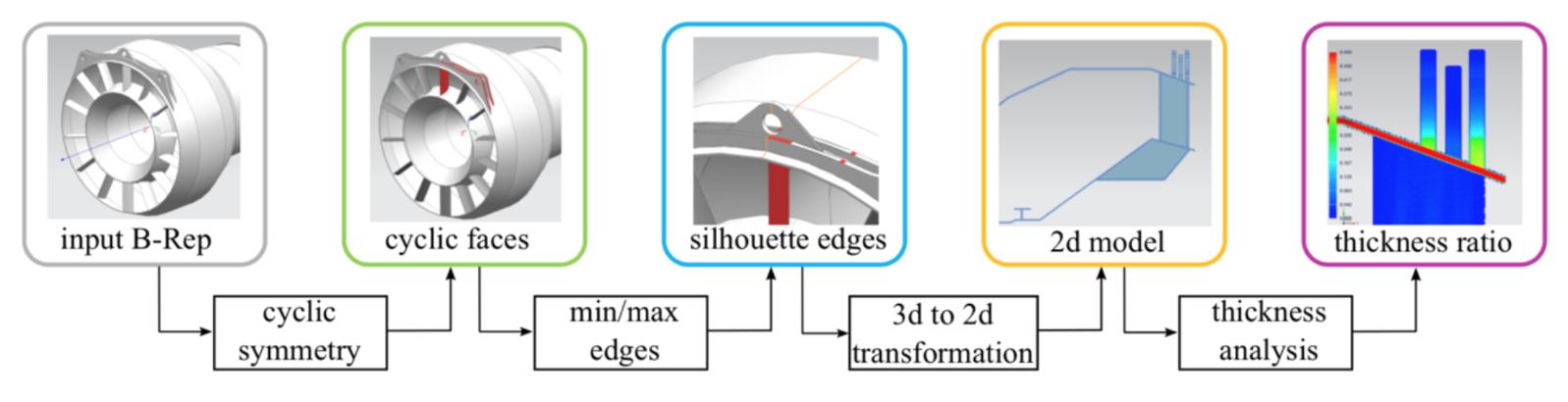
As shown in the Figure above, the proposed method contains four steps. A first step detects groups of cyclic faces of an input B-Rep solid given an axis of rotation, in order to reduce the number of faces and edges to process (see WP1). Before the 3D to 2D transformation, the missing silhouettes edges are generated. These underlying silhouette curves are delimited by the set of points of minimum/maximum radial distance from the axis of rotation to the solid boundaries. Then, the next step applies the 3D to 2D transformation to the solid edges and silhouette edges. This transformation generates a set of 2D curves which are then processed in order to generate the 2D B-Rep model. Finally, the last step generates the thickness ratio field of the 2D model with distinct 2D domains. This thickness ratio field will be associated with the 2D finite element mesh as a simulation attribute. It will also help the user to identify which geometric elements to consider separately in the 2D analysis.
The previous Figure illustrates some results of the proposed approach. The overall method has been implemented in the Siemens NX software package and tested from model import until FE meshing of the B-Rep 2D domains. Future work will need to look at enhanced meshing process automatically identifying details from the analysis of the thickness ratio.
Application of Machine Relational Learning to identify inconsistencies in Digital Mock Ups.
Following the analysis of the use-cases provided by the industrial partner Rolls-Royce, it appears that the received models extracted from Product Lifecycle Management systems contained data inconsistencies such as missing components, duplicated entities, misalignments of parts. A limitation of the ontology-based approach of WP1 is to require consistent CAD models as inputs. Misaligned or missing components stop the application of inference rules. In addition, inferring on a large assembly is time consuming, making this approach difficult to use for quickly identifying the inconsistencies of the CAD models.
Similarly, the pre-processing of digital mock-ups for multi-physics simulation requires identification of components anticipated not to have an influence on the desired results and removing them from the simulation model. Designers and analysts spend considerable time correcting the CAD input assembly in order to obtain a functional assembly model for manufacturing or a model that is fit-for-purpose for finite element analysis and ready to be meshed.
To overcome this problem, we proposed a new approach to help engineers rapidly analyse the consistency of CAD assembly models. In the context of this project, we propose to transcribe CAD models (described as a B-Rep model) as knowledge graphs to learn from. In this work, the RESCAL[1] tensor factorisation model is used as the learning model. Our objectives were:
- To provide quick feedback to the designer/analyst on modelling errors, allowing quick design iteration to correct the CAD model. The authors of RESCAL demonstrated that their model scales linearly with the number of entities. Then, once the factorised model is computed, the user can quickly query if a specific relationship exists or not, essentially in real-time.
- To automatically generate clusters of CAD components to help the user filtering their assembly for a specific analysis and generate a taxonomy of components which can then be used in the simulation intent ontology.
[1] M. Nickel, V. Tresp, H.-P. Kriegel, A Three-Way Model for Collective Learning on Multi-Relational Data., in: ICML, 2011: pp. 809–816.
The method proposed in this work to analyse the consistency of CAD assembly models is decomposed into the following three main steps.
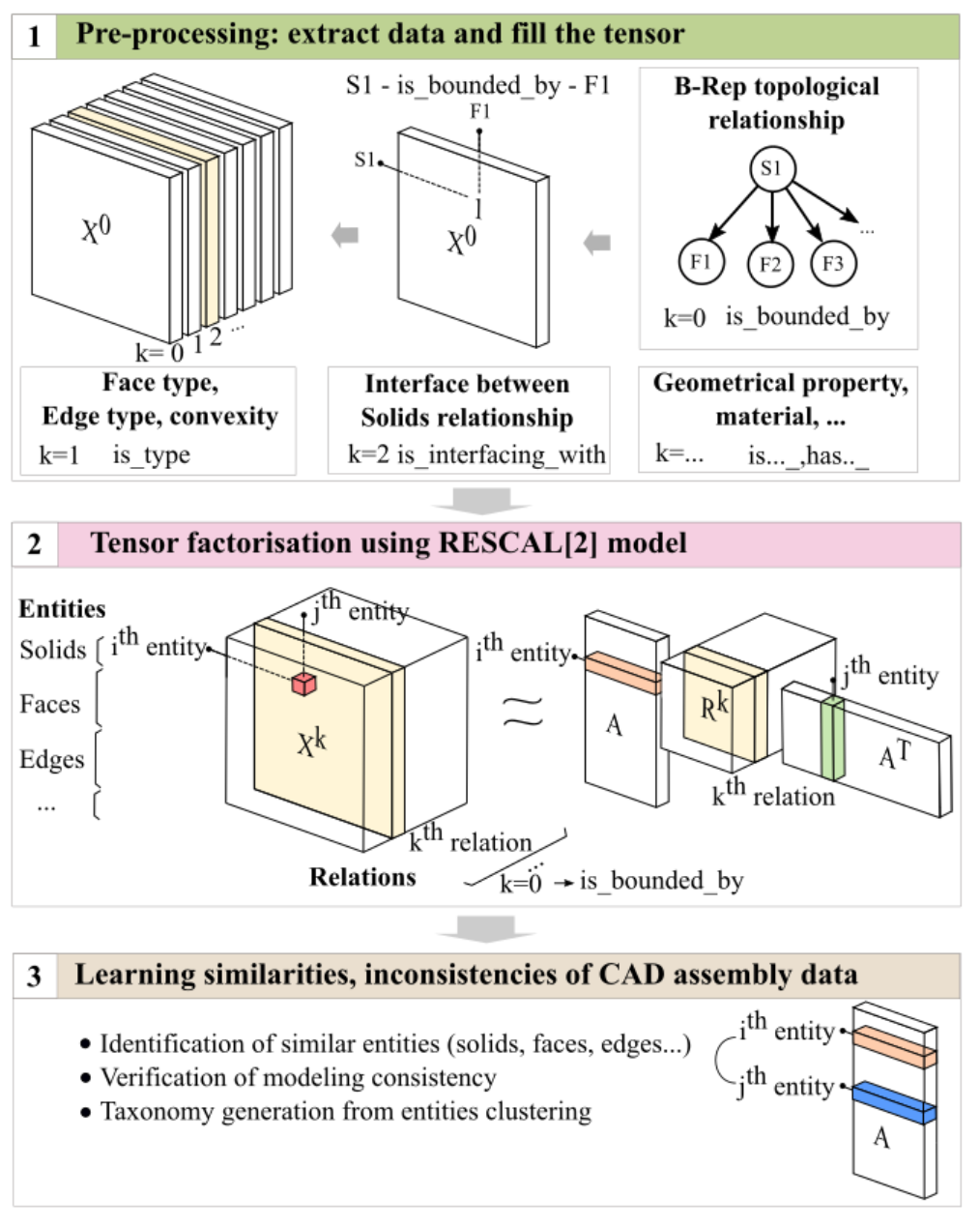
The first step extracts the data from the CAD assembly models. This data is used to populate a three-way tensor which will be factorised in Step 2. The entries of the tensor X on the two first dimensions correspond to the combined entities to analyse. The third dimension contains the different types of relations between the entities which exist in the input CAD models. For example, the first frontal slice contains the topological relations between solids, faces and edges of the B-Rep model. Given the factorization of the initial tensor (step 2), the essential feature of the method is that the latent space A reflects the similarity of entities in the relational domain[1]. Here the similarity of entities refers to the similarities of their relationships. For example: if two solids are bounded by the same type of faces, which are bounded by the same type of edges; if these two solids are also connected to other objects having similar topology, and so on…; there might be evidence that the two solids are identical. Hence, two entities ei and ej can be compared by looking at their individual latent representations ai and aj in A. These latent representations not only measure the common attributes between the entities but also consider the similarity of related entities and relations involved in the relationships of the ith and jth entity.
[1] M. Nickel, Tensor factorization for relational learning, Ludwig-Maximilians-Universität München
Retrieving similar entities in the CAD assembly
The objective is to input an entity: a solid, a face or an edge and to identify which entities are similar to it in the CAD assembly. Similarity refers to the data contained in all relations in the initial tensor. As the topology relations of the CAD components are input in the tensor, together with the connection between the components, two CAD components (i.e. solids) are similar not only because they share a similar topological graph, but also because their similarity is propagated through their connections with the other components in the assembly which also have the same topological graph.
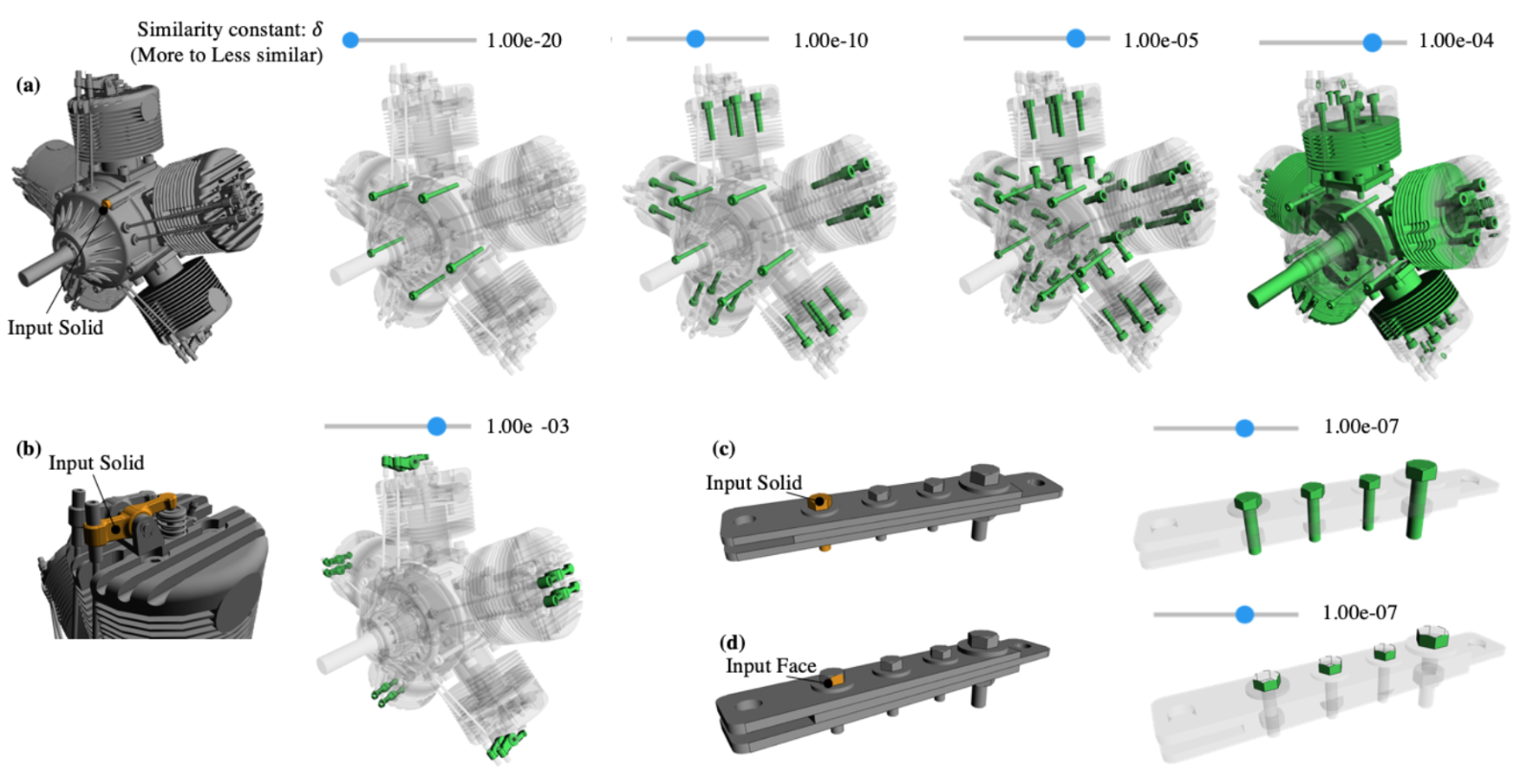
Figure 21 illustrates the application of the method to retrieve similar solids or faces in the CAD assembly models. In the prototype implementation used to test the applicability of the proposed method, a slider component has been designed allowing the user to interactively discover similar objects for a given input. When setting the similarity constant δ to a low value, the method returns only the most similar bolt components. When increasing δ, more components are displayed.
Link-based clustering: building a taxonomy
Following the tensor factorisation, a hierarchical clustering algorithm is used to cluster the entities using their latent representation in A. In this latent-component space, each row of A defines a vector of dimension r. This set of vectors is given as input to a hierarchical clustering algorithm.
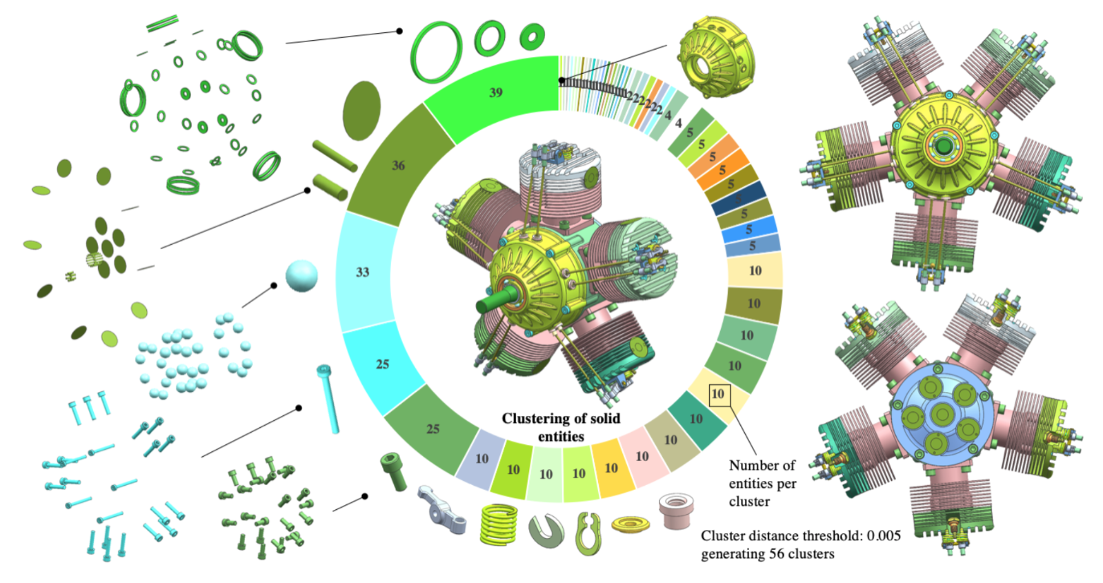
In the context of this work, under the supervision of the user, a CAD assembly model can be analysed and similar entities (components, faces, or edges) can be grouped in order to produce a first taxonomy of components which can then be used in the simulation intent ontology (see WP1). The Figure above shows the result of the clustering for a radial engine model (containing 374 solids) when the threshold is set to 5e-3. The largest clusters contain standard components which are repeated multiple times in the assembly. In this model generating these clusters helps an analyst to easily filter the assembly components.
Identification of modelling inconsistencies
A practical application of our approach concerns the identification of modelling inconsistencies in a CAD assembly. Indeed, when displaying the generated clusters, some entities might not appear in the expected cluster.
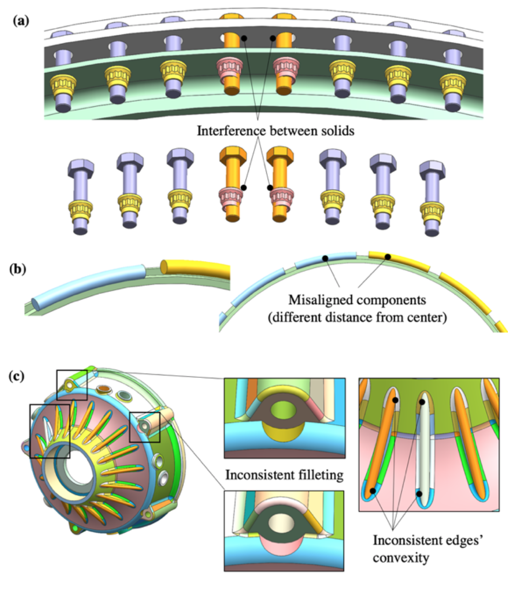
The Figure above shows examples of inconsistencies found in CAD assemblies when analysing the clusters. In (a), two bolts (in orange) are not identified as being part of the bolt cluster. This is because their positioning is not consistent with the other bolts in the component. Their inconsistent positioning generates interferences with their respective nut components, which changes their relations with the neighbouring components. In (b), two groups of components are positioned differently. Here too, this configuration generates different relations for the two groups of components.
Having a consistent CAD assembly is highly valuable for simulation and manufacturing. For example, a finite element simulation of an assembly requires all the contacts between components to be defined. Running a process on a large assembly to automatically apply these contacts requires a clean input model, where all the components are correctly positioned. Our approach provides a low-cost method to help the designer identify modelling issues upfront, without having to interrogate an entire assembly model component by component. Once the model is consistent, it can be input in the ontology-based application of WP1 and all the inference rules can be robustly applied.