MUMPS WP2
Processing CEA symbolic information
In WP1, the simulation intent capabilities have been captured as symbolic information (concepts and relationships) and inserted in the Simulation Intent ontology while maintaining the association to the initial CAD geometry through the cellular model. The purpose of this work package is to illustrate with some common examples how this ontology approach can be used to help the analysts deriving automatically FEM models. Our main application in the scope of this project was the automatic application of boundary conditions for thermos-mechanical simulation.
Inference rules in Simulation Intent ontology
When setting-up a FEM or CFD simulation model, the analyst sequentially applies a series of operations on a CAD model in order to transform it into a simulation model suited for a particular analysis. The choice of geometric transformation, element types, and any simulation parameter is guided through modelling practices. These practices can be formalised in documentation guidelines, however, they are applied informally by the analyst, and are often based on their own modelling experience or company best-practices. With the ontology-based approach, this modelling knowledge can be formalised as inference rules. A set of pre-defined rules can be expressed using the Simulation Intent concepts and relationships described previously. Then these rules can be applied automatically to assist the user in generating the idealisation of an input CAD model.
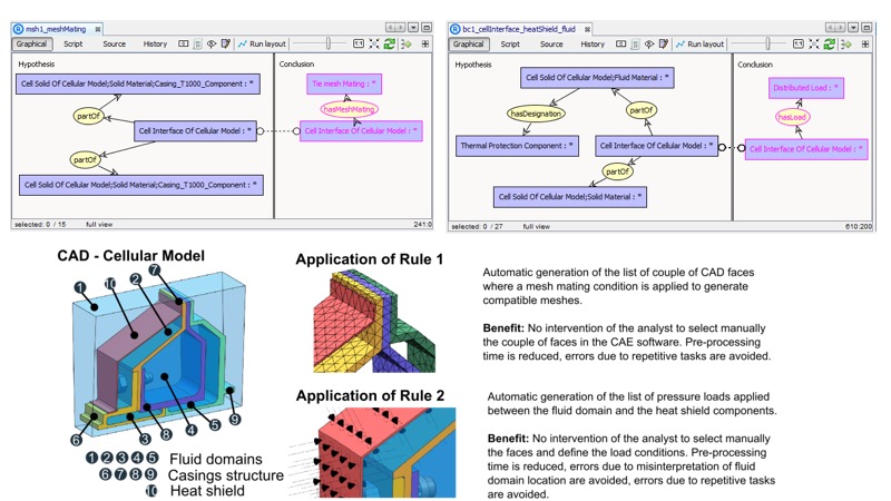
The Figure above illustrates two examples of pre-defined inference rules. These rules can be selected by an analyst to automatically generate simulation and meshing attributes attached to the cells (satisfying the rule conditions). In these examples, the components’ designations, e.g. casing and heat shield, are given by the user using a name tag in the CAD software. This assumption is made in this work to focus on the benefit of using ontology rules to automate certain pre-processing tasks. For example, Rule 1 is associating a tie meshing attribute to all CellInterfaces between casing components. A CAE software, here NX CAE (Siemens plm software 2018a)[1], can query all the interface cells having a mesh mating attribute and automatically apply the condition at the associated pairs of faces. Hence, in a scenario where the solver requires compatible meshes at the components' interfaces, the tedious pre-processing task to manually select all the mating face pairs in the model is avoided, reducing the time to generate the simulation model and avoiding user errors in the selection of faces.
[1] Siemens plm software. 2018a. “NX.” 2018. http://www.plm.automation.siemens.com/en_us/products/nx/index.shtml.
Similarly, Rule 2 associates a pressure boundary condition as a simulation attribute attached to the CellInterfaces between a heat-shield protection component and a fluid domain. Such inference allows the robust location and selection of all the faces of the heat shield component in contact with the fluid domain. In addition, as the cellular model generates the imprints of one object onto another, the tedious task to delimit the fluid domain is also avoided. Currently, the rule does not distinguish between the interior and exterior fluid domains. Future work will develop a geometry processing and partitioning algorithm to distinguish the cavities from the exterior fluid domain in order to enrich the knowledge base allowing the user to specify an even more precise simulation intent.
Application example: Boundary conditions application
The following Figure shows an application example of the simulation intent ontology on an assembly replicating a combustion case section. This model replicates an industrial tedious pre-processing task where the analyst has to manually define a boundary condition at each CAD face in contact with a fluid domain. In a first place, a cellular model is generated using Parasolid (Siemens PLM. 2018b )[1]. Then, the cellular model information, the material as well as the components’ designation (initially entered manually by the user) are extracted and sent as symbolic information to the JENA server. Finally, by selecting pre-defined inference rules the database of facts is enriched with the new facts resulting from the rules. For example, using Rule 2 of the previous section, all the CellInterfaces between a heat shield component and the fluid domain have a new pressure loading attribute.
[1] Siemens PLM. 2018b. “Parasolid.” 2018. https://www.plm.automation.siemens.com/en_us/products/open/parasolid/.
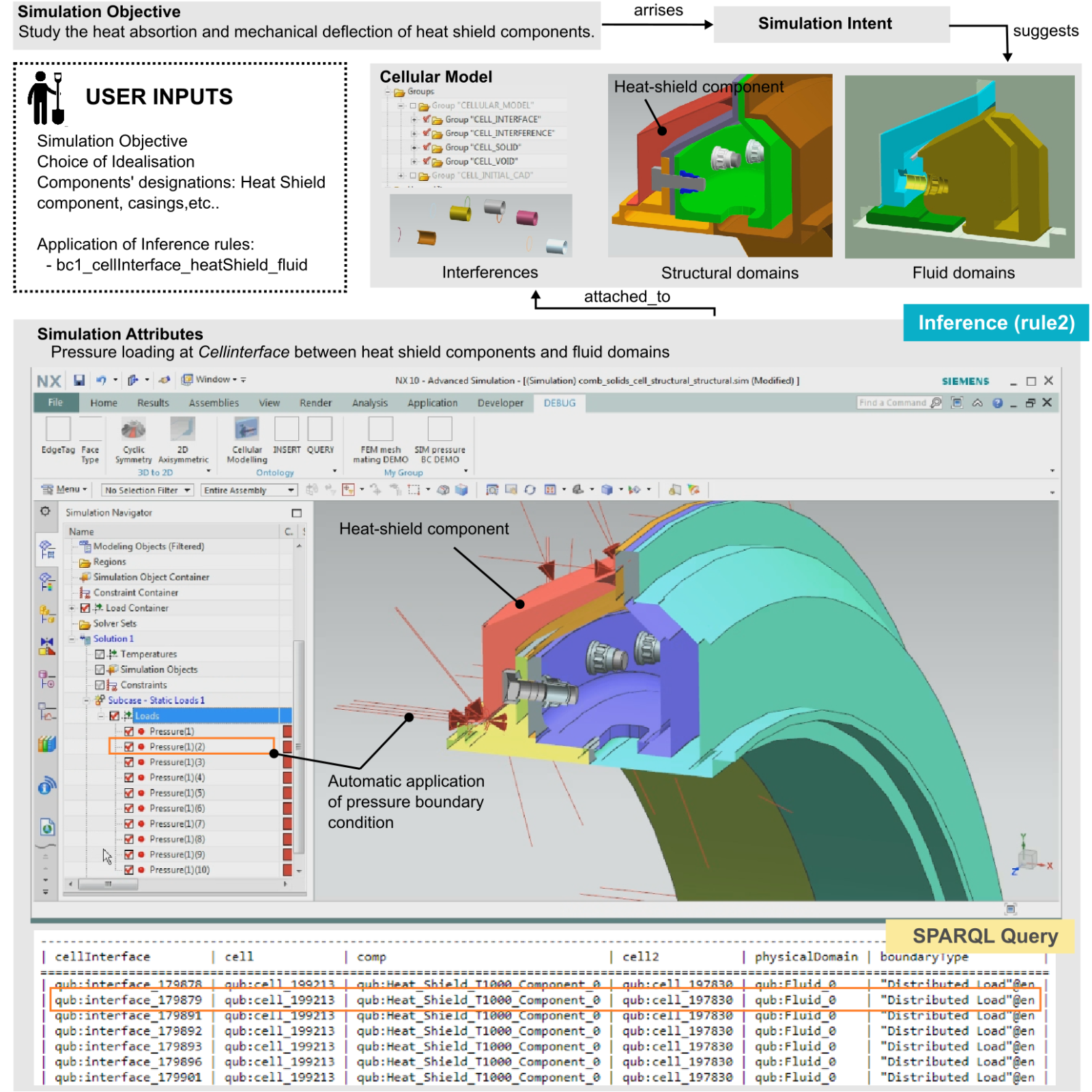
Using a SPARQL query from the NX CAD environment, this information can be used to apply automatically the loading condition to the corresponding CAD faces. If one of the component solids is replaced by a different design, then the SPARQL query can be re-run giving the updated fluid volumes and the new set of faces to which the pressure loading is applied. Interferences are also captured in the cellular model of the assembly, though additional idealisation transformation are necessary before meshing the assembly. In this example, the pressure loads have been generated automatically. In addition to the time saved by the user to manually define the loadings, the ontology-based reasoning robustly locates the entities (here the CAD faces) where these boundary conditions are to be applied.
Application example: Automatic idealisation of components
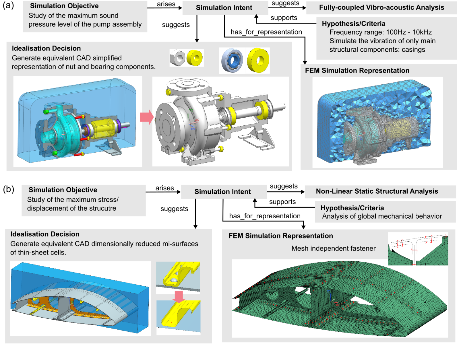
In the following Figure, the standard components, e.g. families of bolts, washers, etc., are of low interest to the analyst. For this analysis type, the user can specify a rule to use a CAD simplified representation for the CellSolid associated with the nut and bearing components. A python script read by the NX software is used to query the components to transform and to automatically generate an equivalent simplified CAD representation. Then, the cellular model is updated to generate the simplified fluid domain to be meshed with tetrahedral elements. This scenario is an example showing how the ontology can be used to robustly define components to idealise based on a pre-defined modelling rule. In the following Figure (b), the idealisation decision concerns the dimensional reduction of thin structural components and the use of mesh independent fastener FE model to define the rivet junctions. A script has also been developed to automatically generate a 1D model from a given 3D rivet and its associated CellInterfaces. In (b), the analyst still benefits from a reduced pre-processing time (especially in the transformation of the 361 rivets). The manual transformation of (b) can be estimated to be two hours compared to several minutes for the automatic process (b)).
These assembly models are examples of particular simulation intent. The selection and choice of simulation parameters (e.g. element type or fastener junctions) to be part of inference rules will depend on the company's approved method and may be defined by the methods engineers. The CAE-oriented ontology approach offers a framework for method engineers to define their preferred formulation through ontology concepts and rules.